
Enabling OSPF
There are 3 ways to enable OSPF and add interfaces to it. The first way is very similar to RIP & EIGRP:
R1(config)# router ospf 1 /* start OSPF process with ID of 1 */
R1(config-router)# network 10.12.13.1 0.0.0.0 area 0 /* just this one interface */
R1(config-router)# network 10.10.0.0 0.255.255.255 area 0 /* local interfaces within range */
R1(config-router)# network 0.0.0.0 255.255.255.255 area 0 /* all interfaces */
The way above works perfectly fine but it is best practice to add OSPF in interface configuration mode:
R1(config)# router ospf 1 /* start OSPF process with ID of 1 */
R1(config-router)# int fa 0/0 /* enter configuration mode for the given interface */
R1(config-if)# ip ospf 1 area 0 /* add interface to given OSPF process & area */
Doing it this way we avoid having to use wildcards. There is also a third way:
R1(config)# router ospf 1
R1(config-router)# passive-interface default
R1(config-router)# no passive-interface gi0/0
R1(config-router)# no passive-interface gi0/1
This way might be faster if there are many interfaces to add to OSPF in disparate subnets. By setting an interface as OSPF passive, it stops sending “hello” messages and trying to bind to neighbours but it will still send LSAs (we’ll see in a bit what these are).
If the current router acts as an ASBR (Autonomous System Boundary Router) gateway to external networks, we can advertise the default route to its neighbours with the same command we use in RIP & EIGRP:
R1(config-router)# default-information originate
Core OSPF concepts: area, DR, BDR, LSAs and LSDBs
An OSPF area is a group of networks that share the exact same LSDB (Link State DataBase) or image of the network topology. Each broadcast domain in an area will choose a Designated Router (DR or primary) and Backup Designated Router (BDR or secondary). Why? If we have a large network with many routers any topology change would lead to a flood of LSAs (Link State Advertisements) from all involved routers. By electing a DR & BDR OSPF avoids that. Any router that is not DR/BDR will become a DROther and will only form adjacencies to the DR & BDR. Let’s see a couple of examples to make sense of it:
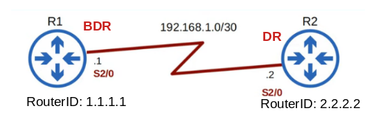
In the simplest case with just 2 routers, one will be the DR and the other one the BDR. The selection criteria is as follows:
1. Highest OSPF priority
2. Highest RouterID
3. Highest loopback interface IP
4. Highest physical interface IP
The default OSPF priority is set to 1 but we can change it on an interface basis with:
R1(config-if)# ip ospf priority 10
In the example above we can assume that the priority for both routers has been left to its default value of 1 so it is the 2nd item in the list that becomes the deciding factor: R2 has a higher RouterID so it becomes the DR and R1 the BDR.
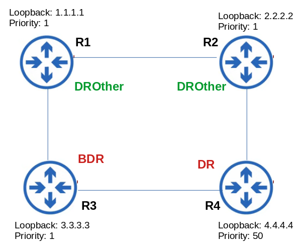
Let’s see a second more complex example:
In the example above the DR designation is easy because of R4’s highest priority. Now, when the RouterID is not explicitly set, OSPF will set it to the highest IP of a local loopback interface or, if there is no loopback interfaces, to the highest IP of any physical interface. In this case then election rules 2 and 3 are effectively the same and R3 wins.
If we know what routers we want as DR & BDR, the easiest way to force the election is simply by giving them the highest and 2nd highest priorities. Even though we can give routers an explicit RouterID like this…
R1(config)# router ospf 1
R1(config-router)# router-id 1.1.1.1
… it is best practice to create one loopback for router and assign it an IP bearing in mind the rules laid out before.
It is important to note two things:
Warning 1: if we assign the Router-ID some time after starting OSPF, then we need to use…
R1# clear ip ospf 1 process
…to enact the change. That might not be a good idea as the router would wipe out all OSPF routes and there would be a delay before they are reloaded. So beware!
Warning 2: once the DR/BDR election is first decided, it will only be redone if the DR or BDR routers go down. DROther routers going offline won’t trigger an election.
• If it is the DR router that goes down, the BDR will be promoted to DR automatically: no election for DR will occur! There will only be an election for the new BDR router.
• If it is the BDR router that goes down, an election for the new BDR will take place.
In a stable OSPF network all routers will have the same LSDB (Link State Database). The LSDB is made up of a series of LSAs (Link State Advertisement) that describe each link in the OSPF area. In other words, an area is a network segment where all routers share the same LSDB image. We can use a single or multiple areas in our network. If we use multiple areas there are some restrictions though:
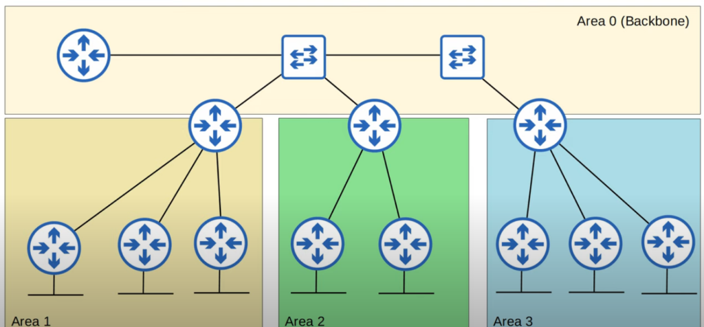
1. There has to exist a backbone area (area 0) that has connectivity to all other areas.
2. All non-backbone areas must be connected to the backbone area. They cannot connect to each other. It must have a Star topology with area 0 in the center.
3. Areas must be contiguous (no splits!)
4. All interfaces in the same subnet must be in the same area
This is an example of a valid OSPF topology compliant with the 4 rules:
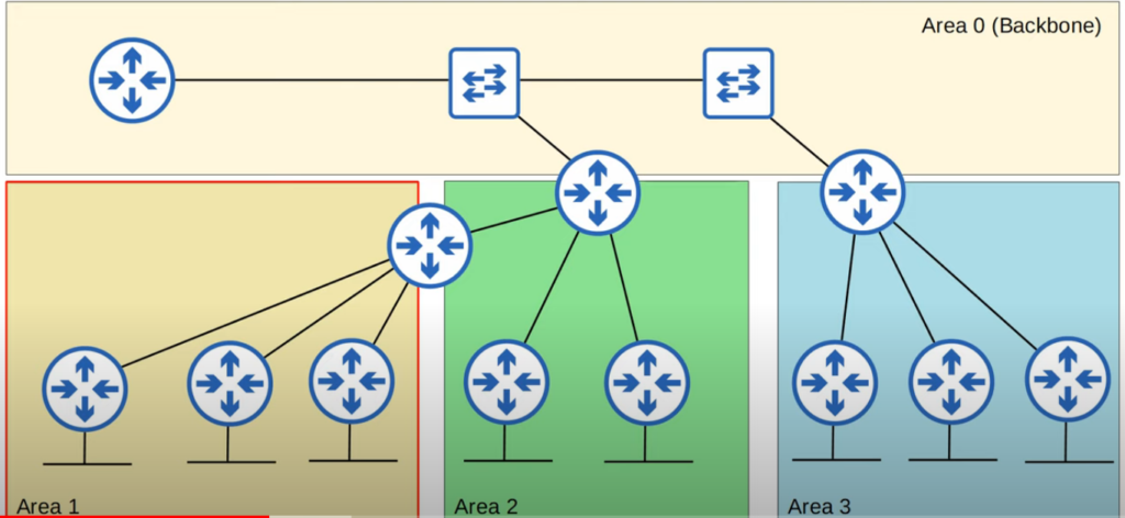
This other example is invalid because it breaks rule 2:
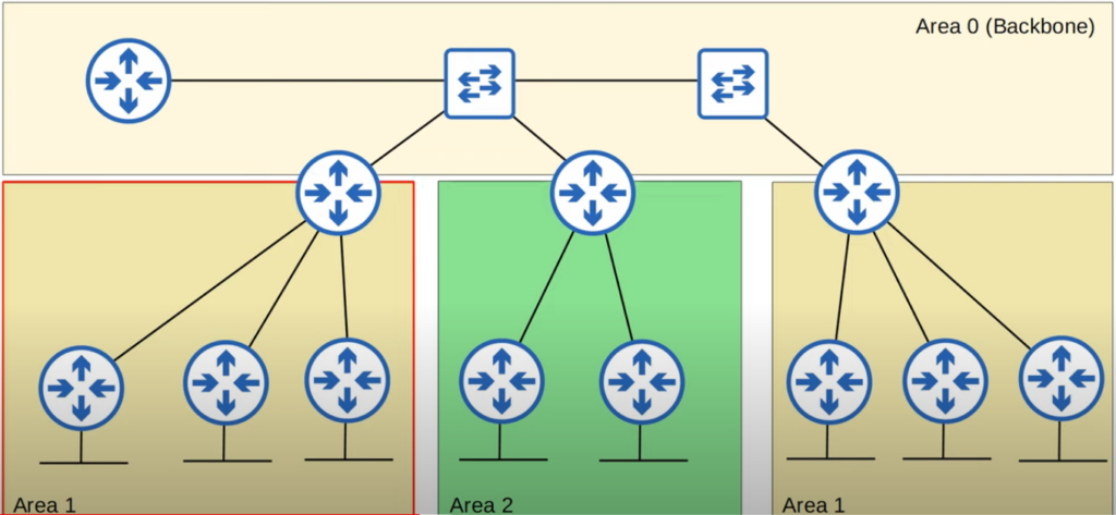
And this one is also invalid because it breaks rule 3:
In the pictures above we see routers that can be classified into 3 categories:
• IR or internal routers: those that are only connected to others in the same area
• ABR or area border routers: those that connect non-backbone areas to the backbone
• BR or backbone routers: are those in the backbone area including the ABRs
Establishing neighbour relationships
Routers using OSPF will form 2 kinds of relationships with fellow routers:
• Neighbours: with all other routers in the same area
• Adjacencies: only to/from the DR & BDR routers in the same area
So in the picture below:
• the DR router will form adjacencies with all other routers
• the BDR router will form adjacencies with all other routers
• the DROther routers will only form adjacencies with the DR & BDR routers
Now, for those relationships to form 8 conditions must be fulfilled:
1. Area number must match
2. Interfaces must be in the same subnet
3. OSPF must be running (the processID does not matter)
4. Router-IDs must be unique
5. Hello & Dead timers must match
6. Authentication settings must match if enabled
7. MTU settings must match
8. OSPF network types must match
If any of the first 6 conditions is not fulfilled, neighbour relationships won’t be formed. If it is any of the latter 2 (MTU or OSPF network type), neighbourship will be formed but routes won’t be transmitted because of a faulty connection.
Assuming all the conditions are complied with, the relationship will be formed in 7 stages:
Neighbour states
1. Down state
2. Init state
3. 2-way state
4. ExStart state
5. Exchange state
6. Loading state
7. Full state
Let’s assume we just enabled the g0/0 interface between R1 and R2 and OSPF is running in both.
• In the Down state the g0/0 interface sends the first Hello message to 224.0.0.5 with Neighbour RouterID destination of 0.0.0.0, meaning “unknown neighbour”.
• In the Init state the interface in R2 receives the Hello message and adds an entry to the OSPF neighbour table for R1.
• In the 2-way state R1 receives the Hello message from R2 and adds it to its OSPF neighbour table. R1 sends another Hello to R2 but this time with its RouterID (and not 0.0.0.0). Now both routers are aware of each other and will become OSPF neighbours once the DR/BDR election is done (no election is needed in PPP networks!).
• In the ExStart state routers will decide who is the master/slave following the same election criteria of DR/BDR.
• In the Exchange state routers will exchange DBDs (DataBase Descriptors) that list the LSAs each router contains in its routing table. At the end of this stage, each router will know what routes it must request to its counterpart to achieve the same LSDB state.
• In the Loading state routers will exchange LSAs. The master will send LSRs (Link State Requests) that will be answered with LRUs (Link State Updates) and acknowledged with LSAck (Link State Acknowledgements).
• The Full state is reached when both routers have identical LSDBs (same routing topology). The Full state will remain as long as the routers keep sending each other Hello messages in the given intervals.
The 7 stages outlined above are only fulfilled when adjacencies are formed between DR/BDR routers and all the rest. If we have 2 DROther routers forming a relationship, they will stop at the end of the 3rd state (2-way) as they won’t exchange LSAs. That’s the main difference between adjacency (ends with both routers in Full state) and neighbour (ends with 2-way).
OSPF timers
In OSPF there are two important timers:
hello-interval: how often are OSPF routes advertised (defaults to 10 seconds)
dead-interval: how many seconds are the routes of a certain source kept before being deleted (defaults to 40 seconds)
If a router does not receive a Hello message for Dead interval seconds from its neighbour, such router will be removed from the neighbour list and its routes wiped out from the routing table. We can change the value for both timers as follows:
R1(config)# int fa 0/0
R1(config-if)# ip ospf hello-interval 15
R1(config-if)# ip ospf dead-interval 60
If we change the hello-interval, the dead-interval will be automatically adjusted to 4x that value. As stated before, both timers must be the same across all routers’ interfaces in the same area. Otherwise neighbour relationships will be broken.
If anything changes in the network topology (e.g. links go down or new ones are added), routers will flood LSAs until all of them reach the exact same LSDB state. By default LSAs age out after 30 minutes after which they will be resent.
OSPF cost or metrics
The core OSPF concept when talking about metrics (RIP/EIGRP) or cost (same meaning for OSPF) is reference bandwidth. This is an integer set by default to a value of 100 (meaning 100Mbps as the benchmark) that is used to calculate the cost of each hop from the local router to the destination. Let’s check an easy example to wrap our head around it:
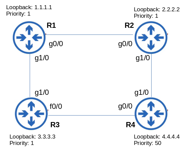
There are 2 routes from 1.1.1.1 (R1) to 4.4.4.4 (R4).
With the default reference bandwidth of 100, the cost of the route via R2 would amount to 3:
– R1 exit g0/0 interface -> (reference bandwidth / interface bandwidth) -> 100 / 1000 = 1 (integer rounded up)
– R2 exit g1/0 interface -> (reference bandwidth / interface bandwidth) -> 100 / 1000 = 1
– R4 jump to loopback interface -> cost 1
– Total cost 3
Same for the other route via R3:
– R1 exit g1/0 interface -> (reference bandwidth / interface bandwidth) -> 100 / 1000 = 1 (integer rounded up)
– R3 exit f0/0 interface -> (reference bandwidth / interface bandwidth) -> 100 / 100 = 1
– R4 jump to loopback interface -> cost 1
– Total cost 3
The cost of both routes comes to the same but it does not make any sense because the link from R3 to R4 is a Fast Ethernet one. So the route via R2 should always be preferred! How do we fix that? Simple: we change the reference bandwidth to a much higher number like 100000.
R1(config-router)# auto-cost reference-bandwidth 100000
Let’s recalculate the cost with that new reference bandwidth:
Route via R2:
– R1 exit g0/0 interface -> (reference bandwidth / interface bandwidth) -> 100000 / 1000 = 100
– R2 exit g1/0 interface -> (reference bandwidth / interface bandwidth) -> 100000 / 1000 = 100
– R4 jump to loopback interface -> cost 1
– Total cost 201
Route via R3:
– R1 exit g1/0 interface -> (reference bandwidth / interface bandwidth) -> 100000 / 1000 = 100
– R3 exit f0/0 interface -> (reference bandwidth / interface bandwidth) -> 100000 / 100 = 1000
– R4 jump to loopback interface -> cost 1
– Total cost 1101
Now the costs look more accurate!
Changing the reference bandwidth and letting routers calculate the route costs is the recommended practice. In certain situations though we might want to increase or decrease the cost of a certain interface because why know something OSPF ignores (e.g. latency, reliability, etc). That can be easily achieved in interface configuration mode:
R1(config-if)# ip ospf cost 500
As a matter of fact, we have 2 more ways to tweak an interface’s cost…
R1(config-if)# bandwidth 100000 /* in kilobits per second */
R1(config-if)# speed 100 /* in megabits per second */
… but both are discouraged for obvious reasons!
OSPF network types
There are 3 OSPF network types:
• Broadcast: this is the default on Ethernet and FDDI interfaces.
• Point-to-point or PPP: enabled by default in PPP and HDLC interfaces.
• Non-broadcast: enabled by default on Frame Relay and X.25 interfaces.
Most of the time we will be working with Ethernet networks so Broadcast will be our OSPF network type. In this type of network everything we have covered in the paragraphs above applies.
When we work with serial networks (PPP/HDLC) the major difference will be the absence of DR/BDR election as it is unnecessary (if one router goes down… the network segment goes down!).
OSPF security
OSPF is insecure by default: if a rogue router fulfills the conditions to form neighbour relationship, it will get the routes to the rest of the network. To tighten security up a notch we can set an authentication password that will have to be known by all routers willing to form OSPF neighbourships:
R2(config)# int g0/0
R2(config-if)# ip ospf authentication-key password123
R2(config-if)# ip ospf authentication
R2(config-if)#
*Oct 30 21:02:45.456 %OSPF-5-ADJCHG: Process 1, Nbr 192.168.1.1 on GigabitEthernet0/0 from FULL to DOWN, Neighbor Down
R2(config-if)# do show ip ospf neighbor
R2(config-if)#
As we can see above, the 1st command sets the OSPF password and the 2nd enforces its use. As a result, the neighbour relationship is cut-off and will remain so until the neighbour also sets the same password on the interface connected to R2.
OSPF show commands
One of the most useful commands to view the OSPF configuration is show ip protocols:
R1# show ip protocols
*** IP Routing is NSF aware ***
Routing Protocol is “ospf 1”
Outgoing update filter list for all interfaces is not set
Incoming update filter list for all interfaces is not set
Router-ID: 1.1.1.1
Number of area in this router is 1. 1 normal 0 stub 0 nssa
Maximum path: 4
Routing for Networks:
Routing on Interfaces Configured Explicitly (Area 0):
Loopback0
GigabitEthernet0/0
GigabitEthernet1/0
GigabitEthernet2/0
Passive Interface(s):
GigabitEthernet3/0
Routing Information Sources:
Gateway Distance Last Update
2.2.2.2 110 00:00:22
3.3.3.3 110 00:00:21
Distance: (default is 110)
The output above shows that this router OSPF has been configured at the interface level (see Routing on Interfaces) and not with the network command. When we use the network command to enable OSPF on interfaces we will see something like this:
Routing for Networks:
10.0.1.0 0.0.0.255 area 0
10.0.2.0 0.0.0.255 area 0
The show ip ospf neighbor lists the RouterIDs, Priority, State, Time to Death, Address and interface of the neighbours:
R1# show ip ospf neighbor
Neighbor ID Pri State Dead Time Address Interface
3.3.3.3 1 FULL/DR 00:00:39 10.0.13.2 GigabitEthernet1/0
2.2.2.2 1 FULL/DR 00:00:29 10.0.12.2 GigabitEthernet0/0
With show ip ospf interface brief we can see what interfaces OSPF is active on:
R1# show ip ospf interface brief
Interface PID Area IP Address/Mask Cost State Nbrs F/C
Lo0 1 0 3.3.3.3/32 1 LOOP 0/0
Gi1/0 1 0 192.168.3.126/25 100 DR 0/0
Fa2/0 1 0 10.0.34.1/30 1000 BDR 1/1
Gi0/0 1 0 10.0.13.2/30 100 DR 1/1
The show ip ospf interface g0/0 displays OSPF settings & metrics for the given interface:
R1# show ip ospf interface g0/0
GigabitEthernet0/0 is up, line protocol is up
Internet Address 10.0.12.1/30, Area 0, Attached via Network Statement
Process ID 1, Router ID 1.1.1.1, Network Type BROADCAST, Cost: 1
Topology-MTID Cost Disabled Shutdown Topology Name
0 1 no no Base
Transmit Delay is 1 sec, State BDR, Priority 1
Designated Router (ID) 2.2.2.2, Interface address 10.0.12.2
Backup Designated router (ID) 1.1.1.1, Interface address 10.0.12.2
Timer intervals configured, Hello 10, Dead 40, Wait 40, Retransmit 5
oob-resync timeout 40
Hello due in 00:00:07
Supports Link-local Signaling (LLS)
Cisco NSF helper support enabled
IETF NSF helper support enabled
Index 1/1, flood queue length 0
Next 0x0(0)/0x0(0)
Last flood scan length is 1, maximum is 1
Last flood scan time is 0 msec, maximum is 0 msec
Neighbor Count is 1, Adjacent neighbor count is 1
Adjacent with neighbor 2.2.2.2 (Designated Router)
Suppress hello for 0 neighbor(s)
The show ip ospf database displays the LSDB:
R1# show ip ospf database OSPF Router with ID (1.1.1.1) (Process ID 1) Router Link States (Area 0) Link ID ADV Router Age Seg# Checksum Link count
1.1.1.1 1.1.1.1 1345 x80000002 0x00FE8D 4
2.2.2.2 2.2.2.2 985 x80000002 0x00FA8D 4
3.3.3.3 3.3.3.3 987 x80000002 0x00FB8D 2
4.4.4.4 4.4.4.4 978 x80000002 0x00FC8D 3
Net Link States (Area 0)
Link ID ADV Router Age Seg# Checksum
192.168.2.3 4.4.4.4 978 x80000002 0x00FC8D
Type-5 AS External Link States
Link ID ADV Router Age Seg# Checksum Tag
0.0.0.0 4.4.4.4 254 x80000002 0x00FC8D 1
Next the show ip ospf displays a mixture of metrics on the OSPF process and the areas it is attached to:
SW1# show ip ospf 201
Routing Process 201 with ID 192.0.2.1 VRF default
Stateful High Availability enabled
Graceful-restart is configured
Grace period: 60 state: Inactive
Last graceful restart exit status: None
Supports only single TOS(TOS0) routes
Supports opaque LSA
Administrative distance 110
Reference Bandwidth is 40000 Mbps
Initial SPF schedule delay 200.000 msecs,
minimum inter SPF delay of 1000.000 msecs,
maximum inter SPF delay of 5000.000 msecs
Initial LSA generation delay 0.000 msecs,
minimum inter LSA delay of 5000.000 msecs,
maximum inter LSA delay of 5000.000 msecs
Minimum LSA arrival 1000.000 msec
Maximum paths to destination 3
Number of external LSAs 0, checksum sum 0
Number of opaque AS LSAs 0, checksum sum 0
Number of areas is 2, 1 normal, 1 stub, 0 nssa
Number of active areas is 0, 0 normal, 0 stub, 0 nssa
Area (0.0.0.10) (Inactive)
Area has existed for 00:12:18
Interfaces in this area: 0 Active interfaces: 0
Passive interfaces: 0 Loopback interfaces: 0
This area is a STUB area
Generates stub default route with cost 25
Simple password authentication
SPF calculation has run 1 times
Last SPF ran for 0.000122s
Area ranges are
Area-filter in ‘FilterLSAs’
Number of LSAs: 0, checksum sum 0
Area (0.0.0.15) (Inactive)
Area has existed for 00:20:18
Interfaces in this area: 1 Active interfaces: 0
Passive interfaces: 1 Loopback interfaces: 0
No authentication available
SPF calculation has run 1 times
Last SPF ran for 0.000020s
Area ranges are
Number of LSAs: 0, checksum sum 0
We can delete specific OSPF routes or all OSPF provided routes:
R1# clear ip route 10.11.12.0 /* deletes specific route */
R1# clear ip route * /* deletes all routes so table will need to be rebuilt */
We can alse reset a specific OSPF process or all of them:
R1# clear ip ospf 1 process /* resets ospf process 1 so neighbours, database and routing table will need rebuilding */
R1# clear ip ospf process /* resets all ospf processes so neighbours, database and routing table will need rebuilding */
Finally, we have a few debugging tools at hand if we need to dig in and resolve OSPF problems: